- Important benefits OOPS programming in C++
Encapsulation- Securing data in single unit in form of class.
Data Abstraction- Creating new user defined data types modeling real world entities complete with built in data type properties and allowed operators.
Inheritance- Allows a sub class to inherit the properties of the base class. Help avoid the problem of rewriting the code again and again in a program.
Multiple Inheritance- Type of inheritance where there are multiple base classes each with its own instance variable
Polymorphism- Single name/operator associated with multiple operations depending on the type of data. It is done by operator overloading, function overloading and dynamic binding (virtual functions).
Message Passing- It invokes an operation on an object by passing a message
Genericity- It is declaration of data items without specifying data type. It is done when the data type is not fixed and varies according to the data passed to it. Example is sort() function. It is realized through function templates and class templates.
Delegation- Based on the object view that an object can be a collection of multiple objects and relationships. That is it has a has a relationship or containership relationship. It is quite similar to inheritance in that it passes (delegates) a receiving operating to its delegate.
Persistence- Object outlives the existence of its program execution period and exists during the program execution too. Supported in C++ by use of file streams.
Extensibility- This is what is done by inheritance and abstract classes. They allow the extension of a software or function.
Showing posts with label Educational. Show all posts
Showing posts with label Educational. Show all posts
Friday, January 3, 2014
C++ important interview questions and exam notes


Wednesday, December 25, 2013
Android multiple choice objective questions
Android multiple choice questions
- To perform inter-communication between activities or services ______ is required:
- Binder
- Intent
- AIDL
- Service
- How to set a launcher activity?
- using application node in AndroidManifest.
- using Layout node in main.xml
- using string.xml
- None of the above
Saturday, November 9, 2013
Best institutes and subjects for CDAC and placement opportunities
CDAC (Center for Development of Advance Computing) is a Government established program which is both a research center and a training institute. With its center at Pune and branches across Indian, CDAC has a became a preferred choice for students of Engineering and MCA to get excellent placement opportunities in case they are not able to get them from then Bachelor or Master’s degree program. It is also a good choice for professionals who want to improve their resume by adding a plethora of programming languages in their skill set. Let’s see the best CDAC Intitutes (Those highlighted in red color are placement centers):
Embedded in another good field to go for. Integrated VLSI and Embedded is a tough field because it covers 2 subjects and it is quite difficult to cover these 2 subjects in 6 months. Effectively, there is only 4.5 or 4 months of study in CDAC with the rest devoted to exams and project time.
- Banglore (Knowledge Park)- Pune might be the center of CDAC but due to the presence of more programming related industries in the area and the southern habit of making you work like anything, Banglore has the best placements. Please do note that CDAC was started with the “DAC” course and even now the main focus of CDAC is on DAC only. DAC department is given the best faculty and all efforts of the institute are focused on them, be it placement or teaching. This is the same for all CDAC institutes. Classes are of around 9 hours starting from 9 AM in the morning and you won't get any holiday except of national holidays.
- Pune- Pune being the headquarter and present in south, the southern culture makes the students work like anything. You will be having classes from 9 AM in the morning to anywhere till 8-9 PM all 7 days of the week. Holidays will be rare and you should expect them only during national holidays.
- Hyderabad- Hyderabad is also a IT hub and will get you excellent placements. Present in south the students are given a heavy toll of work just like in Banglore and Pune.
- Banglore- The second branch of CDAC in Banglore also gets the benefit of many IT industries present in south and again the southern culture of studying.
- Noida- CDAC Noida is also present in industrial area and is one of the placement centers. However, the placement scenario is not as good as other CDAC centers mentioned above. DAC department February 2013 batch got around 10 placements and other departments excluding the Embedded department had almost negligible placements. Embedded department had around 50% placement track courtesy a number of embedded industries located in Noida and Gurgaon. This center has Saturday and Sunday off with the class timing from 9.30 AM to 5 PM.
Subjects to select
If you are just going for placements then DAC is the subject to go for. CDAC doesn't put much efforts in the other branches and that is the reason for poor performance of these branches. If you are really interested in some other subject then you will have to make it amongst the toppers of the class and become efficient in programming to get any chances of placement.Embedded in another good field to go for. Integrated VLSI and Embedded is a tough field because it covers 2 subjects and it is quite difficult to cover these 2 subjects in 6 months. Effectively, there is only 4.5 or 4 months of study in CDAC with the rest devoted to exams and project time.
Placement opportunities
Placement opportunities have been talked about in the center listing itself. As for the companies, CDAC offers the companies trained professionals which require very less training from the company side to get them started in the job. This is the reason why companies prefer to employ good candidates from CDAC centers. Many famous IT companies like TATA, Infy, etc come to CDAC centers. The main focus of these companies the knowledge of the students in C, C++ and Java. It is important to keep a focus of Aptitude too as most companies have this test as the first shortlisting method. Company list is more center specific and changes with every batch and if you are in the first 4 centers mentioned above, you need not worry about the companies but should just focus on becoming as efficient in programming as possible.Saturday, September 29, 2012
Uses of multiplexer and demultiplexer
Multiplexer
In communication field, the methods by which many inputs (the inputs may be analog or digital in form) are combined together to give one output is known as multiplexing. Multiplexing is a technique to select one suitable output from the given number of input lines . Another terminology in multiplexers are the section lines. The output is determined with the help of selection lines .
The selection lines are dependent on the type of multiplexer. There are various types of multiplexer namely
For example: We use frequency division multiplexing for cable television ,voice telephony requirements etc. time division multiplexing or time division multiple access(TDMA) for 2G and 3G systems. Whereas, in prior versions of 2G, known as code division multiple access(CDMA), we were using code division multiplexing.
Uses of Frequency Division Multiplexing (FDM)
When the total bandwidth or frequency available is divided into a set of frequency which should be non-overlapping, this technique is known as frequency division multiplexing (FDM). Each subset is used to carry different signals. This allows the common medium to be shared by many different frequencies. You all must be watching television as a daily part of your life which works with the help of cable wire, it is the most extensive and common example of frequency division multiplexing in real life. The television channels which are nothing but frequencies are carried by one single cable which is the medium.
Uses of Time Division Multiplexing (TDM)
When the message to be sent is differentiated with a very short time lag or when the packets to be sent takes turn on the channel such as one packet is transmitted during the time slot 1 , the second is transmitted at slot 2 and so on. This technique of transmitting and receiving of the data while taking turns on the time is known as Time Division Multiplexing.
This type of multiplexing is mainly used in telephone networks like in circuit switch networks namely public switch telephone network (also known as landline) in which there are multiple subscribers, and if all the lines are full at a particular time then we are not able to make the call. But if we try after some time our call gets connected!! This is mainly because during the time one or more subscriber hangs the phone creating the vacancy of the medium at that time.
Uses of Code Division Multiple Access (CDMA)
This is a technique in which several users are successfully able to transmit and receive the data simultaneously that is at the same time over the same frequency. So in contrast to FDM and TDMA which divides access by frequency (wavelength) or time respectively, code division multiple access is spread spectrum signaling.
For example: Many people speaking in a room can hear and understand your particular language and all other languages are considered as noise. In the same way in CDMA, each user is given a code, in a single channel there are many codes but the users who are connected to the similar code only can communicate.
This code is used in the GPS systems and signaling for mobile networks.
Demultiplexer
In electronics, a demultiplexer is a device which takes the output from a single line and directs it to several output lines. It is used when we need to send the same output to several lines or to several devices. Mainly demultiplexer is required to break the single data stream to the original data streams.
Also, the main aim of a demultiplexer is to combine the data and to transmit it over the medium by taking in single input and making the information to exit through multiple outputs.
Note: We are in process of finding more uses for Demultiplexer, if you happen to know more than please add the info in the comments and help your co-students!
In communication field, the methods by which many inputs (the inputs may be analog or digital in form) are combined together to give one output is known as multiplexing. Multiplexing is a technique to select one suitable output from the given number of input lines . Another terminology in multiplexers are the section lines. The output is determined with the help of selection lines .
The selection lines are dependent on the type of multiplexer. There are various types of multiplexer namely
- 2-to-1 multiplexer(having 1 selection line)
- 4-to-1 multiplexer(having 2 selection lines)
- 8-to-1 multiplexer(having 3 selection lines)
- 16-to-1 multiplexer(having 4 selection lines).
For example: We use frequency division multiplexing for cable television ,voice telephony requirements etc. time division multiplexing or time division multiple access(TDMA) for 2G and 3G systems. Whereas, in prior versions of 2G, known as code division multiple access(CDMA), we were using code division multiplexing.
Uses of Frequency Division Multiplexing (FDM)
When the total bandwidth or frequency available is divided into a set of frequency which should be non-overlapping, this technique is known as frequency division multiplexing (FDM). Each subset is used to carry different signals. This allows the common medium to be shared by many different frequencies. You all must be watching television as a daily part of your life which works with the help of cable wire, it is the most extensive and common example of frequency division multiplexing in real life. The television channels which are nothing but frequencies are carried by one single cable which is the medium.
Uses of Time Division Multiplexing (TDM)
When the message to be sent is differentiated with a very short time lag or when the packets to be sent takes turn on the channel such as one packet is transmitted during the time slot 1 , the second is transmitted at slot 2 and so on. This technique of transmitting and receiving of the data while taking turns on the time is known as Time Division Multiplexing.
This type of multiplexing is mainly used in telephone networks like in circuit switch networks namely public switch telephone network (also known as landline) in which there are multiple subscribers, and if all the lines are full at a particular time then we are not able to make the call. But if we try after some time our call gets connected!! This is mainly because during the time one or more subscriber hangs the phone creating the vacancy of the medium at that time.
Uses of Code Division Multiple Access (CDMA)
This is a technique in which several users are successfully able to transmit and receive the data simultaneously that is at the same time over the same frequency. So in contrast to FDM and TDMA which divides access by frequency (wavelength) or time respectively, code division multiple access is spread spectrum signaling.
For example: Many people speaking in a room can hear and understand your particular language and all other languages are considered as noise. In the same way in CDMA, each user is given a code, in a single channel there are many codes but the users who are connected to the similar code only can communicate.
This code is used in the GPS systems and signaling for mobile networks.
Demultiplexer
In electronics, a demultiplexer is a device which takes the output from a single line and directs it to several output lines. It is used when we need to send the same output to several lines or to several devices. Mainly demultiplexer is required to break the single data stream to the original data streams.
Also, the main aim of a demultiplexer is to combine the data and to transmit it over the medium by taking in single input and making the information to exit through multiple outputs.
Note: We are in process of finding more uses for Demultiplexer, if you happen to know more than please add the info in the comments and help your co-students!
Sunday, August 26, 2012
Different types of synchronous counters, ciruit diagram and working
There are 6 types of Synchronous counters:




Binary counters
Binary counters are most basic type of synchronous counters. Depending on the value of N, a synchronous counter counts from 0 to (2N - 1) and back to 0 again.
Up/down counters
A counter can be used to count in more than one direction. That is, you can use counter to count not only up but down too. The diagram shows below is of an up-down counter. Depending on how the user decides to count an event as up and other as down, the counter can be used to count the events based on his requirements. This is done by either making either the “up” or "down" inputs as high.Loadable counters
Loadable counters can be used to count from a predefined count. That is, instead of counting from a 0, the counter will count from a initial count given by the user. This type of counter is called a loadable counter.BCD counters
A BCD counter is a binary digit based counter which users 0 and 1 for counting. The counting is done in binary-coded decimal from 0000 to 1001 and back to 0000. As the counter resets after 1001, i.e. it starts from 0 and after a count of 9 it comes back to 0. Therefore, this counter does not have a straight binary count and has limited functionality.Ring counters
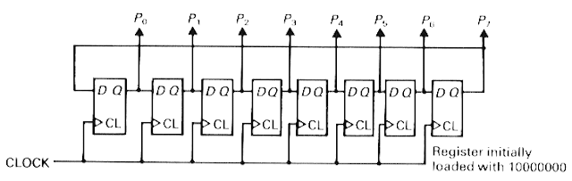
In a ring counter, the registers are activated one by one in a circular manner. The flip-flops are set one by one; when a particular flip-flop is set, the others are cleared. A single high signal is circulated from one flip-flop to another to produce to produce the sequence of timing signals.
Johnson counters
The Johnson counter is a hybrid form of ring counter. It is also called the twisted ring counter. In this counter the inverse of the most significant bit output at the flip-flop is passed on to lest significant but at the flip-flop. The working can be understood by the truth table shown below. The sequence starts with all the bits of the counter being 0. At the next pulse, the 0 at the final counter will cause the 1’s to be shifted into register from left hand side. Similarly, when the 1’s reach the most significant flip-flop, 0’s will be inserted in the left most registers. This cross coupling between the between the inputs and the outputs of the registers is the base of working of the Johnson counter.

Thursday, April 5, 2012
Different types of transducer and their application in Engineering
Transducer over view
Technically a transducer1. Input device
2. Signal conditioning and processing device
3. And an output device
In these three parts the input devices performs the function of receiving the quantity which going to be measured, called measurand, and converts it into some other analogous form generally electrical from and hands it over to the second stage i.e. signal processing section where some operations are performed upon this input signal like:
- Amplification
- Attenuation
- Filtration
- Modulation/modification into some other acceptable form
Monday, April 2, 2012
Details about what is Anthropomimetic robotic technology
Advancement
in robotic technology has gone so high that even routine jobs in
industries have been replaced by robots. However the initial cost for
set of such robotic workers in industries is costlier but the outcome is
much more beneficial as compared to the man labor.
Because of its extent of resemblance with the human it reduced the man to machine gab and tries to bring both at the same level in many spheres of industrial and professional lives.
Because of its extent of resemblance with the human it reduced the man to machine gab and tries to bring both at the same level in many spheres of industrial and professional lives.
OVER VIEW OF ANTHROPOMIMETIC MACHINES
In our following discussion we will be concerned at a new class of the robotics which is Anthropomimetic Machines which are characterized by their ability of responding to external stimuli mentally and capability of performing the allotted task.Types of electronic display devices and their advantages and disadvantages
In
this article I have given detailed description about different types of
display devices and their working along with their comparison with
other display devices.
1. Planer devices
2. Non-planer devices
Display Devices
Display device, that is used to display some visible massage, may have several types depending upon several criteria. One criterion for their classification is formatting of the display, thus there can be two type of display devices based upon the format are:1. Planer devices
2. Non-planer devices
Monday, December 26, 2011
Use of different magnets in Magneto therapy
Magnets used in magneto therapy
Magnetic field in human body the basis of the magneto therapy according to which there is a net inward and outward flow of magnetic field in the body and balancing between this to and fro flow of magnetic field leads to a healthy body. Any disordering in magnetic field in any part of the body leads to different types of ailments in order to re-establishing proper flow of magnetic flow in those parts external magnets can be applied depending upon their size, strength and shape. Some of the mostly used magnets are listed below.Types of magnets in magneto therapy
1) Rolling pin magnets: As the name suggests these are thin at the two edges and round in the midst. These are used in curing serious internal injuries and pain, sciatica, acute cough etc. They are used on the body by rolling them on affected parts.2) Square shaped magnets: They look like weight and are square shaped. These are generally used on face i.e. pain in eyes and cheeks are cured by putting these magnets on those parts. Pain in fingers is also cured by their application.
3) U-shaped magnets: These, being u-shaped, are used to examine the decease a different parts of the body. Pain in stomach and headache is cured by these magnets.
4) Flat magnets: these sheet like magnet flat in shape and due to it simple shape are used to cure most of the deceases i.e. these are multi-purpose magnets.
5) Rolling pin magnet with hole: when an central hole is bores in rolling pin magnet it yields this type of magnet it is also used in the same way as the rolling in magnets except some deceases.
6) Ring like magnets: These are shapes as ring because of their application as they are worn in gingers of either hand. The ring magnet formed with eight metals is considered to be best magnet and serves the purpose of healing in better way. These are capable of curing pain in wrist and ears. It is also used to give relief in the problems like when urine accumulates in kidneys and does not pass through them properly.
7) stick shaped magnets: The magnets having shape of a stick is also used in magnetotherapy but rarely but these are generally used by the scientists in laboratories for caring out many experiments.
8) Saw magnets: These are also rarely used magnet and generally used for curing the pain in bleeding places in body like joints.
9) Horse shoe magnets: These type of magnets also have very good medical application in curing different deceases but mainly these are used by veterinary doctors for curing animals like cow, buffaloes and cats.
10) Weight shaped magnets: These being in shape of weight are the most prevalent now a days because these are the magnets very easily available in metro cities These are available in different types depending upon their power of magnetism i.e.
a) High power magnet for adults
b) Medium power magnets for boys and girls between 3 and 16 years
c) Low power magnets used for children under 3 years and also used for curing eyes, nose and throat.
11) Neck belt magnets: As the name tells about its application it is worn in neck to cure different deceases of neck like throat cough, tonsillitis and bronchitis. Also by wearing it in neck for 15 to 30 minutes it is capable of curing spondylitis.
12) Head belt magnets: These are tied around the forehead and when used twice a day for 15 minutes it relieves headache, intolerable pain in forehead, mental weakness an s other deceases of head.
13) Eye magnets: These are very light weight magnets with low magnetic power which ensures no over-magnetisation to eyes which may even damage them in spite of curing them. These are to be used for 15 minutes regularly for proper healing of eye decease.
14) Knee belt magnets: It is lied on the knees to give relief to the knee problems like inflammation and its dislocation. For proper curing the decease it should be used half an hour in morning and for an hour in evening.
15) Magnetic belt for back and stomach: These are comparatively larger in size and having large magnetic power used for curing decease of back and stomach like: backache, slip disc, dislocation, hernia, pain in stomach, kidney inflammation and other urinary disordering.
16) Necklace magnets: It contains ceramic or silver made magnetic beads in from of an necklace to be worn in neck. It relieves many deceases like cold, cough, asthma, chest decease etc. These are very helpful in curing various deceases but it is a bit costlier.
17) Blood pressure magnetic belt : This is worn in wrist in order to control the blood pressure problems. These are made of high power magnetic pieces embedded in the watch like structure. One precaution should be done before using them that person suffering from high blood pressure should wear that belt in right hand which is generally marked with R and this R sign should touch the pulse of wrist similarly person suffering from low blood pressure should wear it in left hand wrist which is marked with a L sign and this sign should be touching the pulse.
18) Magnetic chair: Here two magnets are embedded on the back side of it and one magnets in each of its hands such that upper magnet on back side having north pole and lower one having south pole and right hand magnet with north pole while left hand having south pole. A person should sit on this chair for about half an hour on daily basis. It is useful in curing the decease of back and hand.
Black hole wiki, creation of blackhole and its effects
Black hole is nothing but an object having very high gravitational force so that even light having so much velocity does not succeed to escape from it if once caught in side it. It has such dimensions that it is concentrated at a point only with all its mass this is referred to as singularity and due to so strong gravitational force at such a small point makes this singularity such that time and space crushes together and becomes indistinguishable i.e. looses their independent existence. The gravitational force decreases with the increase in distance from it which depends upon the mass of singularity. The influence of the gravitational force can also be seen from the fact that the minimum velocity required by an object to escape from its force of attraction while passing from neighbourhood at minimum possible distance is equal to velocity of light. And his minimum required distance makes its "horizon" i.e. something like its surface through which its existence may be defined in free space beyond the singularity point. And any object that comes within this horizon gets trapped inside it and gets lost forever within the instance gravitational force.
Formation of black holes
When an object attains a certain high critical density producing such a high gravitational force make it collapse within its and giving it infinitely small point size. The time when a massive star is not capable of producing energy in its core it leads to formation of the Stellar- mass black hole i.e. it the energy generating in its core causes to counter balance the gravitational force of its mass so in absence of this mass it collapses at this time two situations are possible either the outer layers of the star blast out and move into the free space of to fall inside the formed black hole and strengthen it by making it more massive. Still the formation of the massive black holes is not clearly known, there are many estimations about its formation like maybe they are formed due to collapse of the large gas clouds or it may be a result of fusion of many small black hole to form a large one.Black holes in universe
Many super massive blacks have been found in the nearby galaxies and many at far distances like quasars in our own galaxy, i.e. Milky Way, a dozen or two stellar black holes have been identified also some intermediate mass galaxies have been found in Milky Way and also in nearby galaxies. The super massive black holes are usually found at the centre of the most galaxies causing all the other mass revolving around it and some stellar black holes anywhere in the galaxy. In this way thousands of such black are there in the galaxies presently known.Method to prepare magnetized liquid with uses and health benifits
Just
like the other materials when placed under magnetic field gains
magnetism in the same way water and oil also gets the property of magnet
when placed under magnetic field for a considerably large time of
period and thus obtained magnetized water or magnetized oil can be used
for curing various diseases.
Magnetized liquids can also be prepared at home by some simple methods for which some important ingredients are:
Basic ingredients required :
2) Baby of about years should take two spoons a day.
3) A child of three years should take three spoons at a time and trice a day.
4) A child of twelve year should take a cup of water a day.
5) A adult should take two ounces at a time and twice a day.
2) In case of the person suffering from fever may take it after two hours.
1) It is used to improve the digestive process and increases the appetites flow in liver and reduced the excess of acids in stomach.
2) Improvement in movement of bowels is obtained by magnetized water and it expels poisons and unwanted materials from the body.
3) It cleans the arteries and normalizes the circulation system within the body and stabilizes the functioning of the heart.
4) In the case of a patient suffering kidney problem when the urine accumulates in there, by taking 25 ml of magnetized water along with equal quantity of plan water for 8 to 10 times a day makes the proper flow of the urine.
5) It washes the kidneys and gall-bladders by removing salty and unwanted materials from them.
6) All kind of fever, pain, asthma, bronchitis, colds, coughs and headache can be healed by using magnetized water.
Magnetized oil
Oils can also be magnetized in the same way the water is done and used for healing purpose for an example yellow mustard oil and sesame oil can be magnetized.
In magnetized oils there are some most common working examples like:
North Pole magnetized oil helps in healing boldness, weakness and paralysis likewise South Pole magnetized oil is used for healing diseases like asthma, skin diseases, insomnia, and all kind of pain.
Oil magnetized by both the poles is used in body and hair massage and it should be rubbed on the hands.
Magnetized liquids can also be prepared at home by some simple methods for which some important ingredients are:
Basic ingredients required :
- Two powerful magnets having round shape and for satisfactory work their power should be around two to three Gauss.
- Two glass to keep the water while magnetizing it.
- A large, clean bottle to store the magnetized water.
- Plane and fresh drinking water.
Method to prepare magnetized water
Taken the fresh water it should be clean for which boil it and then cool it down and fill both the glasses with this water. Put the magnets on the wooden plank in such a way that North Pole directs towards north and south pole of the magnet point towards south on the plank. Now put the glass at the center of the magnets and cover the gasses with some plastic or wooden cover to prevent the water to be contaminated. Keep the glasses in this position for about a whole day to make the water get magnetized properly to be used for healing purpose. Transfer the water in a bottle. Some precautions are to be taken here that the magnets should not be put inside the water and water in the bottle should be filled up to neck.Dosages
1) One year old infant should take one spoon a day.2) Baby of about years should take two spoons a day.
3) A child of three years should take three spoons at a time and trice a day.
4) A child of twelve year should take a cup of water a day.
5) A adult should take two ounces at a time and twice a day.
Time of taking it
1) It is suggested to take this water in morning before the breakfast and after taking the heavy food of afternoon and evening.2) In case of the person suffering from fever may take it after two hours.
Benefits of magnetic water
Magnetized water can be used in healing innumerable diseases like indigestion, nervous and urinary system by using it magnetic property which is also scientifically approved. Some of the most common benefits of magnetized water are listed below:1) It is used to improve the digestive process and increases the appetites flow in liver and reduced the excess of acids in stomach.
2) Improvement in movement of bowels is obtained by magnetized water and it expels poisons and unwanted materials from the body.
3) It cleans the arteries and normalizes the circulation system within the body and stabilizes the functioning of the heart.
4) In the case of a patient suffering kidney problem when the urine accumulates in there, by taking 25 ml of magnetized water along with equal quantity of plan water for 8 to 10 times a day makes the proper flow of the urine.
5) It washes the kidneys and gall-bladders by removing salty and unwanted materials from them.
6) All kind of fever, pain, asthma, bronchitis, colds, coughs and headache can be healed by using magnetized water.
Magnetized oil
Oils can also be magnetized in the same way the water is done and used for healing purpose for an example yellow mustard oil and sesame oil can be magnetized.
In magnetized oils there are some most common working examples like:
North Pole magnetized oil helps in healing boldness, weakness and paralysis likewise South Pole magnetized oil is used for healing diseases like asthma, skin diseases, insomnia, and all kind of pain.
Oil magnetized by both the poles is used in body and hair massage and it should be rubbed on the hands.
Magnetism in planets and humans
Magnetic field associating planets and humans
All the planets are made of different light and heavy elements with them involved an many natural activities occurring in them. These also consists of the metals like iron, silver, gold, cobalt and many other good conductors at the time of their formation all these raw material keeps revolving around the star(sun) due to centripetal force acting upon them all these materials gets condensed to form a solid material revolving extraterrestrial body called planets. Due to condensation of so enormous amount of mass a large amount of heat is generated which rises the temperature of the planet very large at the time of formation but with the passage of time temperature falls down whining the same time light element comes at the ground and heavy metals forms the core of the planet being at a very high temperature, and having molten state, due to revolving nature of the planet at the time formation the hot molten core keeps spinning inside the solid outer light element.Now as we know that when some charge moves with an velocity it creates an magnetic field around at and when it revolves in a circle it makes an magnet at the two faces of the circle. Similarly the metal core heated to such a high temperature liberates its electrons and make the core like a huge charge revolving in a large circle. This creates a large amount of magnetic field around the planet which is so strong that it also affects other planets.
Magnetic power of sun
The sun is a large natural magnet having its impact over all the members of our solar system. Due to its strong attraction force at controls the movement and orbits the planets revolving around it. The living object on earth like plant and animals are nourished with it. Sun being at a very high temperature produces bunches of heat and magnetic field, called reflex, which received by all the planets including earth affecting each and every particle on it.Magnetic force of moon
Moon also has its magnetic field of its own which influence e other planet. Earth being nearest to it is most affected by it, in such a ways that its many significances can be seen in our daily life for example the tidal waves are also created by them attraction force of moon due to which water in sea gets attracted by moon and wave gets enormous height. Now as seventy percent of the human body is just water then no objection comes out to be logical against the fact that humans are affected the attraction force of moon.Magnetic force of earth
Just like other planets earth also has it magnetic force around which makes it like large magnet with its magnetic north and south poles this being so powerful obviously affect the activities occurring in it including the living organisms. This magnetic field is responsible for following activities1) The hazardous electromagnetic radiations, containing ultra violet radiation and enormous heat, coming from sun gets reflected by the magnetic field of earth which makes a environment on earth favourable for development of life on it.
2) Magnetism of earth also helps the some bird in finding their path while fling in air and their destiny while their seasonal flights from one continent to the other in absence of which they can never find the right direction to move in.
3) Earth magnetism has also been used by the marine navigator in finding their way in open sea for a long time but now a day satellite mapping is use to serve the purpose.
4) It also neutralizes the ionised gases in upper portion of the atmosphere in absence of which enormously large static charge will accumulate in atmosphere whose discharging to earth will cause a very high energy thunder attacks anywhere on earth.
5) The solar storm coming from sun are reflected by earth magnetic field which if enter earth atmosphere can destroy all the electronic gadgets in it including satellite, power stations, radio stations, communication systems and everything that uses electronics in its operation.
Magnetism in human body
All the extraterrestrial bodies have magnetism due to revolving metallic core within them. In the same way magnetic field is also existing in all the living thing whose origin in actually the nervous system present in them which governs and controls all the activities performed by it. The central point of the nervous system is brain which takes the massages from all senses in from of electrical signals and sends appropriate command to organs after processing them. This whole task is done with the help of neurons connected with each other and conveys the signal from one to the next one by movement of charged ions, like Na, within them. As is described above that moving charge creates magnetic field thus these moving charges ions also produces magnetic field of its own. As the this magnetic field it generated because of the nervous system and nervous system is present in the whole body making a network so magnetic field also comes out to be present in each and every part of the body making a definite pattern. This pattern forms a magnetic body present inside the physical body we live in.Magnetism in human body is so produced that magnetic poles appears in it as:
1) The head and upper half of the body is taken to represent NORTH POLE and opposite i.e. feet and lower half of the body are taken to represent the SOUTH POLE.
2) Now considering the body horizontally right side of the body is considered to be NORTH POLE and left as SOUTH POLE .
3) Similarly front side of a person consisting of forehead, face, chest an d belly is considered to be NORHT POLE and the back is taken as SOUTH POLE .
This magnetic behaviour exhibited by human body it is affected by the magnetic fields of planets which forms are basis of the whole astrology which actually studies the effects of planets on invisible magnetic body of humans. Taking this whole discussion leads us to the conclusion that there is a balancing between the outer and inner magnetic field of the body and proper in and out flow of this magnetic field leads to proper well going of the body. Any misbalance between to and fro movement of the magnetic field may cause an ailment in physical body. For keeping well flow of magnetic field through the body following precautions the advised to take.
1) One should keep the body in accordance to the outer magnetic field of earth while sleeping such that head staying in south and feet in north direction to make proper flow of magnetic field through the body.
2) A person just going to die should be made to lie on ground such that head in north and feet towards the south direction to facilitate escape of the life force from the body and a painless death.
Tuesday, October 25, 2011
How to practically differentiate from AC to DC current
Practically differentiating AC current from DC current
Theoretically AC current is one which when passed through a conductor the polarity of the current at the two ends of the conductor keeps changing with a fixed frequency i.e. at a time if current is flowing in one direction then after sometime(a fraction of second) it will be flowing in the opposite direction and so on. While in case of an DC current polarity of the current at the two ends of the conductor remains same throughout the time i.e. current flows only in a single direction(from positive terminal to negative terminal).We can use this property, of changing the conduction direction, for detecting whether the current flowing in a conductor is AC or DC. There are many many ways of doing this in which some easiest ones are listed below which can be done very easily and also can be understood how they work. These methods require the instrument which are easily available in market , very cheap, one can use them easily with basic electronic knowledge:
Before going for the testing you must set the multimeter is appropriate rage for example if the input supply(to be tested) is estimated to about 80- 100 V you should set it in 200 V(AC) range, if it is estimated to be around 200- 250V you should set it in 1000V(AC) range, remember you always have to keep multimeter in AC voltage ranges and not in current mode otherwise multimeter may be damaged.
1) The easiest method is to use an diode because it is an unidirectional device. For this you need to have a multimeter, be it digital or analogue and a diode 1N4008 because its reverse break down voltage is 1000 V. Now connect one terminal of diode with one end of input supply and other one with the meter(set in appropriate range). Now connect other end of input supply with remaining terminal of meter and see whether meter is showing any voltage or not. Now reverse the terminals of diode and see whether meter is showing any voltage or not. If meter shows voltages in both the cases then it is AC current in input supply otherwise if it shows voltage in only one case(first or second) then it is DC current.
2) This method requires no diode but applicable manly for small voltages. Here to must have a analogue multimeter and all you need to do is that set the meter in 50V(DC) range and connect it directly to the input supply. if the needle of meter remains still at a level (further or behind the 0 reference level) then it is DC and if at keeps fluctuating or vibrating near 0 reference level then it is AC.
3) This method requires a speaker of about 25 ohm, and a variable resistor which is available in market and known as vilume. Take a volume of resistance around 10-100 ohm. Connect the terminals of input supply to the two extreme ends of volume and also connect the first and last terminal of volume with speaker. Rotate the volume knob if any beep sound is heard then it is AC but if only a single click sound is heard then it is DC. There are also many other ways for differentiating AC from DC current but the methods listed above are simplest ones
Working of Zener diode as voltage regulator
Voltage regulator is actually a circuit which receive a D.C. voltage at input fluctuating up and down in a range, depending upon the characteristics of the zener diode used and the other components, and gives an constant voltage (app.) at the output which can be, further, fed into some other circuits e.g. amplifier, oscillator etc where a constant supply of D.C. voltage, of fixed value, is required for well functioning.
Basic principle of working is non linearity of the diode i.e. resistance of the diode does not follow ohm's law according to which the voltage varies linearly with current through resistor and resistance remains constant for all values of the voltage applied across the resistor. While in case of the diode resistance drops as the voltage increases across it. So, the actual characteristic of diode that is used for voltage regulation is its variable resistance (i.e. its voltage dependence). As the diode, being used as voltage regulator, works in reverse bias, so, it is its breakdown voltage which decides the output voltage which can also be as low as 5V which can be easily obtained from a zener diode but not a rectifier diode.
Working of rectifier: When the fluctuating voltage Vin is applied at the input as shown in the figure it passes through resistor R and diode so the applied voltage gets divided between the resistor R and the diode such that voltage across zener diode is Vz (break down voltage) and that across resistor is (Vin – Vz) i.e. the applied voltage gets divided between the resistor and the diode by the law of potential division depending upon the resistance ratio. Now when positive fluctuation occurs i.e. voltage increases slightly same increase appears across diode, let it be (Vz+v), but as only a very small increase in voltage across diode causes its resistance to drop so in against to the increase in voltage it resistance gets reduced but that of the series resistor remains constant and thus resistance ratio gets chanced. According to the new ratio the new increased voltage is now so divided such that voltage across diode decreases from (Vz+v) to about Vz. The same process occurs each time the input voltage fluctuates.
Basic principle of working is non linearity of the diode i.e. resistance of the diode does not follow ohm's law according to which the voltage varies linearly with current through resistor and resistance remains constant for all values of the voltage applied across the resistor. While in case of the diode resistance drops as the voltage increases across it. So, the actual characteristic of diode that is used for voltage regulation is its variable resistance (i.e. its voltage dependence). As the diode, being used as voltage regulator, works in reverse bias, so, it is its breakdown voltage which decides the output voltage which can also be as low as 5V which can be easily obtained from a zener diode but not a rectifier diode.
Working of rectifier: When the fluctuating voltage Vin is applied at the input as shown in the figure it passes through resistor R and diode so the applied voltage gets divided between the resistor R and the diode such that voltage across zener diode is Vz (break down voltage) and that across resistor is (Vin – Vz) i.e. the applied voltage gets divided between the resistor and the diode by the law of potential division depending upon the resistance ratio. Now when positive fluctuation occurs i.e. voltage increases slightly same increase appears across diode, let it be (Vz+v), but as only a very small increase in voltage across diode causes its resistance to drop so in against to the increase in voltage it resistance gets reduced but that of the series resistor remains constant and thus resistance ratio gets chanced. According to the new ratio the new increased voltage is now so divided such that voltage across diode decreases from (Vz+v) to about Vz. The same process occurs each time the input voltage fluctuates.
Monday, September 26, 2011
Pin description and working of IC: NE555

Working of timer IC: NE555
This IC can be used in many ways like timer, multivibrator(in astable mode), as a flip-flop(in bistable mode). It was designed by Hans R. Camenzind in 1970 and brought to market in 1971 by Signetics (later acquired by Philips). The original name was the SE555 (in metal can) and NE555(in plastic DIP) and the part was described as The IC Time Machine . It is believed that the 555 gets its name from the three 5 kO resistors used in typical early implementations, but Hans Camenzind has stated that the number was arbitrary.The part is still in wide use, due to its easy use, good stability and low cost.
An standard 555 package available in markets contains over 20 transistors, 2 diodes, and 15 resistors on a silicon chip all in a single 8-pin mini package(IC). now a number of different form od NE555 is present in market depending upon the number of pins and number of timers present in them some of which can be listed as below:
Pin desrciption
1) 556 : It has 14 pins, combination of two 555 having Vcc and ground connections commen.
2) 558 : It has 16 pins, combination of four 555 timer ICs with DIS, THR and power connections in common.
Functions of all 8 pins of NE555:
1) pin 1 (GND) : It is always grounded i.e. connected to negative terminal of battery.
2) pin 2 (TRIG) : This pin is use for triggring the timer on when an negative pulse is applied at it by means of an push button(remember only a input negative pulse is needed to triggger the timer and not a continuos negative potential supply)
3) pin 3 (OUT) : The output supply pulse is obtained from this pin of a specific width and time periode which is decided by the resistor connected at THR and DIS.
4) pin 4 (RESET) : When an negative pulse is given to this pin it resets the timer and begins it from starting, so it is generally connected to positive(when not in use) of the battery to avoide any miss-functioning of the circuit.
5) pin 5 (CTRL) : This pin is generally not used and remains unconnected because it controls voltage, allows access to the internal voltage divider (2/3 VCC).
6) pin 6 (THR) : This is the pin which dicides the potential at OUT pin i.e. when potential at pin 6 is atleast 2/3 Vcc it gives an lower potential at OUT othewise if potential at pin 6 is less than 2/3 Vcc higher potential appears at pin OUT.
7) pin 7 (DIS) : Potential at this pin is also decided by THR pin i.e. when potential at THR is atleast 2/3 Vcc then is pontential reduced to Zero(i.e. it is grounded), and provides a discharge path for capacitor C.
8) pin 8 (Vcc) : This pin is always connected with positive input supply which must be between 3-15v for working of IC safly and reliably.
Working of the IC as a time in monostable mode:
For the IC to work as a timer pins 8 and 4 are connected to positive input supply which is generally 5-9V, pin 1 is grounded, pin 3 is connected to output circuit(if any), pin 7 and 6 are connected togather and given a positive supply from the source through a resistor R and also connected to ground throuth a capacitor C such that R and C form a potential divider and give a specific voltage at pin 7 and 6. As capacitor C charger with time i.e. its effective resistance increases wiht time so by the potential divider rule potential at pins 7 and 6 increases with time with a specific time rate which depends upon values of R and C.
Pin 2 is initially connected to positive terminal through a resistor of about 5 Kohm. As soon as, pin connected to negative potential of battery, for a while, timer starts working i.e. capacitor C starts discharching through R and potential at pin 6 increases. At the same time a higher potential appesres at pin 3 and it remains high as long as the potentia at pin 6 reaches 2/3 Vcc i.e. when the potential reaches 2/3 Vcc pin 3 is shifted to lower potential i.e. no output is obtained at pin 3 after thet time. At the same time potential at pin 7 reduces to Zero(i.e. connencted to ground), so, capacitor discharges through pin 6, instantaneously, and resets the timer for next time. When, again, pin 2 is connected to negative potential consanguineously the same functioning repeats itself.
Principle and Working of SCR (silicon controlled rectifier)
This
article mentions the detailed working of SCR(silicon controlled
rectifier ) with application, characteristics and parameters affecting
it.
SCR, It is actually an thyristor which is used to control the high voltage supply as compared to the conventional transistors. It is an four layered P-N-P-N semiconductor three terminal device, such that all the four segment arranged in a single array. it has an anode, cathode and an gate terminal. The upper P-type semiconductor is termed as anode ,usually given an positive voltage, the lower N-type semiconductor segment is termed as cathode and usually given an negative voltage while p-type semiconductor near cathod is gate which supplied with an positive pulse to trigger the device.

There are three modes of opearation for an SCR depending upon the biasing given to it:
a) Forward blocking mode(off state)
b) Forward conduction mode(on state)
c) Reverse blocking mode(off state)
a) Forward blocking mode: In this mode of operation anode is given an positive potential while cathode is given negative voltage keeping gate at zero potential i.e. disconnected. In this case junction J1 and J3 are forward biased while J2 is reversed biased due to which only a small leakage current flows from anode to cathode till applied voltage reaches it breakover value at which J2 undergoes avalanche breakdown and at this breakover voltage it stars conducting but below breakover voltage it offers very high resistance to the flow of current through to it and said to be in off state .
b) Forward conduction mode: SCR can be brought from blocking mode to conduction mode in two way either by increasing the voltage across anode to cathode beyond breakover voltage or by application of positive pulse at gate. Once it stars conducting no more gate voltage is required to maintain it in on state. Now there are two way to turn it off i.e.
* Reduce the current flowing through it below a minimum value called holding current .
*Apply an negative pulse at gate which will bring it in off state instantaneously.
c)Reverse blocking mode: In this mode anode it supplied with negative and cahtode with positive voltage which reverse bias J1 and J3 and no current passes through it.
It can be used in many ways dependinding upon its operation in the circuit.
1) As the name suggests it can be used as an rectifier which offers low resistance in direction while high resistance in opposite direction just like an ordinary diode but difference is that for the conduction in one direction it also requires an positive gate pulse. But while using it as an rectifier does'n prove to very useful because the output wave form obtained is distorted.
As per shown in figure:1 the input ac power obtained from the transformer in fed between anode and cathode while gate is supplied with an positve voltage by the application of an diode upon it though the resistor, both togather givev only a small positive voltage to the gate. Now, when positive half half cycle appeares across the transformer it produces positive potential to anode and negative potential at cathode and at the same time small voltage also appear across gate which triggers the SCR and current conducts from anode to cathode while when negative half cycle appears across transformer it make anode negative, cathode positive and gate is given negative pulse which completely revers bias the SCR and no current flows though it. Thus, it produces half wave rectified output. it cannot be used for rectification of samall voltages(2-6V) because in conduction state an voltage appears across it which is around 1-2V so a major drop in output waveform will be seen if used for small voltages.
 2) The second major application is as an switching device,
in which when an positive pulse is given at gate the SCR stars to
conduct current from anode to cathode. But here it can be used only for
DC power source.
2) The second major application is as an switching device,
in which when an positive pulse is given at gate the SCR stars to
conduct current from anode to cathode. But here it can be used only for
DC power source.
 Note One very important parameter affecting working of an SCR is its dV/dt
value that rate of chance of anode to cathode voltage with respect to
time. Very high value of dV/dt causes the SCR trigerred before its
breakover voltage and can result in undesired triggering of the device
there is always a maximum possible value of dV/dt for avoiding any
undesired triggering of SCR and it can be different for defferent SCRs.
Note One very important parameter affecting working of an SCR is its dV/dt
value that rate of chance of anode to cathode voltage with respect to
time. Very high value of dV/dt causes the SCR trigerred before its
breakover voltage and can result in undesired triggering of the device
there is always a maximum possible value of dV/dt for avoiding any
undesired triggering of SCR and it can be different for defferent SCRs.
SCR, It is actually an thyristor which is used to control the high voltage supply as compared to the conventional transistors. It is an four layered P-N-P-N semiconductor three terminal device, such that all the four segment arranged in a single array. it has an anode, cathode and an gate terminal. The upper P-type semiconductor is termed as anode ,usually given an positive voltage, the lower N-type semiconductor segment is termed as cathode and usually given an negative voltage while p-type semiconductor near cathod is gate which supplied with an positive pulse to trigger the device.

Modes of operation of an SCR
There are three modes of opearation for an SCR depending upon the biasing given to it:
a) Forward blocking mode(off state)
b) Forward conduction mode(on state)
c) Reverse blocking mode(off state)
a) Forward blocking mode: In this mode of operation anode is given an positive potential while cathode is given negative voltage keeping gate at zero potential i.e. disconnected. In this case junction J1 and J3 are forward biased while J2 is reversed biased due to which only a small leakage current flows from anode to cathode till applied voltage reaches it breakover value at which J2 undergoes avalanche breakdown and at this breakover voltage it stars conducting but below breakover voltage it offers very high resistance to the flow of current through to it and said to be in off state .
b) Forward conduction mode: SCR can be brought from blocking mode to conduction mode in two way either by increasing the voltage across anode to cathode beyond breakover voltage or by application of positive pulse at gate. Once it stars conducting no more gate voltage is required to maintain it in on state. Now there are two way to turn it off i.e.
* Reduce the current flowing through it below a minimum value called holding current .
*Apply an negative pulse at gate which will bring it in off state instantaneously.
c)Reverse blocking mode: In this mode anode it supplied with negative and cahtode with positive voltage which reverse bias J1 and J3 and no current passes through it.
Application of SCR
It can be used in many ways dependinding upon its operation in the circuit.
1) As the name suggests it can be used as an rectifier which offers low resistance in direction while high resistance in opposite direction just like an ordinary diode but difference is that for the conduction in one direction it also requires an positive gate pulse. But while using it as an rectifier does'n prove to very useful because the output wave form obtained is distorted.
Working as an rectifier
As per shown in figure:1 the input ac power obtained from the transformer in fed between anode and cathode while gate is supplied with an positve voltage by the application of an diode upon it though the resistor, both togather givev only a small positive voltage to the gate. Now, when positive half half cycle appeares across the transformer it produces positive potential to anode and negative potential at cathode and at the same time small voltage also appear across gate which triggers the SCR and current conducts from anode to cathode while when negative half cycle appears across transformer it make anode negative, cathode positive and gate is given negative pulse which completely revers bias the SCR and no current flows though it. Thus, it produces half wave rectified output. it cannot be used for rectification of samall voltages(2-6V) because in conduction state an voltage appears across it which is around 1-2V so a major drop in output waveform will be seen if used for small voltages.

V-I characteristics of SCR
It has very different characteristics in forward and verese biases as is seen in figure:2 . in forward bias it has- Forward blocking region: In which SCR offers very high resistance.
- breakover voltage: At this voltage it changes its state form off state to on state.
- Holding current: This is the minimum current required to maintain it in on state.
- Latching region: In this region it remains in conduction mode and a voltage of 1-2V appears across it.
Tuesday, September 13, 2011
What is the functioning, use, construction and working of Electronic multimeter?
It is a very versatile meter in laboratories because it can
be used for many purposes. Some of its functions are DC and AC current and
voltage measurement and resistance of resistors used in electronic circuits. The
solid state version is described here in oncoming discussion. Following
components are constituent parts of a multi-meter.
·
A balance bridge DC amplifier and PMMC indicator
·
A range switch which is an attenuator to limit
the value of input voltage to the desired one.
·
A rectifier on order to convert AC to equivalent DC value
·
An internal battery and additional circuitry for
the measurement of resistance.
·
A function Switch to reset various measurement
functions for the instrument like current, voltage and resistance.
Along with this all the instruments has a built in power
supply for the purpose of performing operation on power mains and many cases
one or more than one batteries for operation as portable test instrument. Here
is figure that is capable of showing all the part that has been discussed about
in our discussion so far.
 |
| Balanced DC amplifier |
This figure shows the schematic diagram of a balanced bridge
DC amplifier that uses two field effect transistors (FETs). These two FETs are
reasonably matched with each other on the basis of current gain this done to
ensure thermal stability in the circuitry. The upper arm of the bridge is
formed with the help of two FETs the source resistors R1 and R2 together with
zero adjustment of resistor R3 form the lower bridge. The PMMC instrument is
connected between the source terminals of FETs. These two FETs represent two
opposite end of the bridge. In case of no input signal applied to the gate
terminal of FETs they remain to be at the zero potential or ground potential. In
this case in ideal situation there should be no current flowing through the
meter. But due to presence of some miss matches between the FETs and also due
to some differences in values of resistor a current does flows. This unwanted
current can be reduced to zero with the help of a grounded variable resistor.
Subscribe to:
Posts (Atom)